

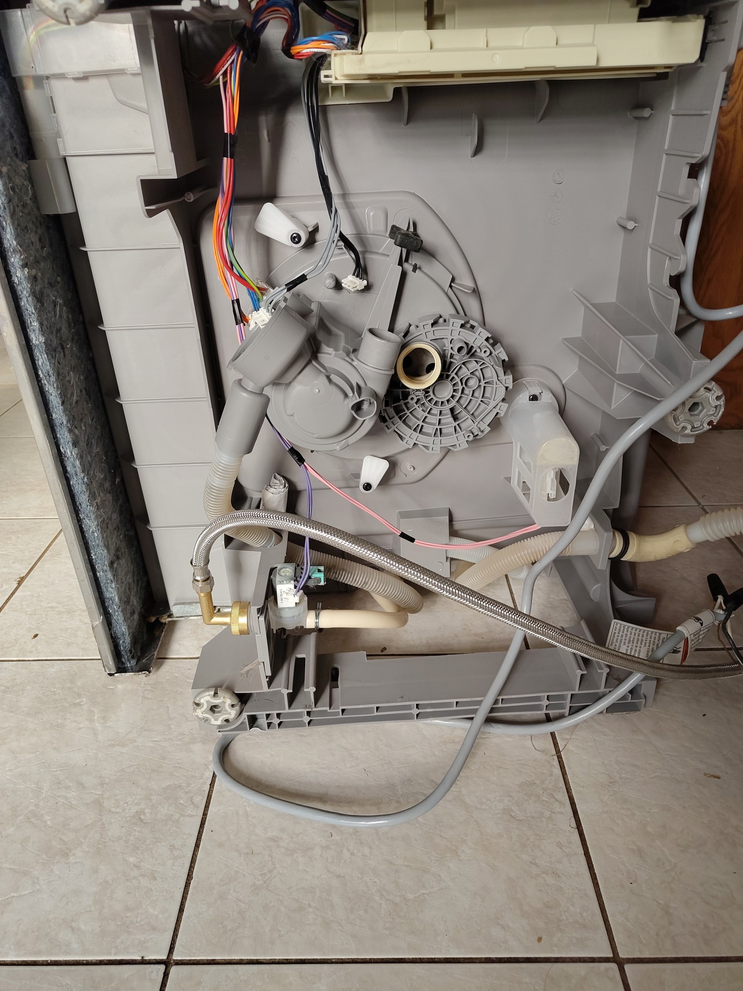
Part of trying the get my dishwasher to drain https://piefed.ca/c/diy@slrpnk.net/p/894317/help-fixing-my-dishwasher-it-won-t-drain-and-is-stop-on-sanitize-mode
I have removed to drain pump, solenoid, water heater.
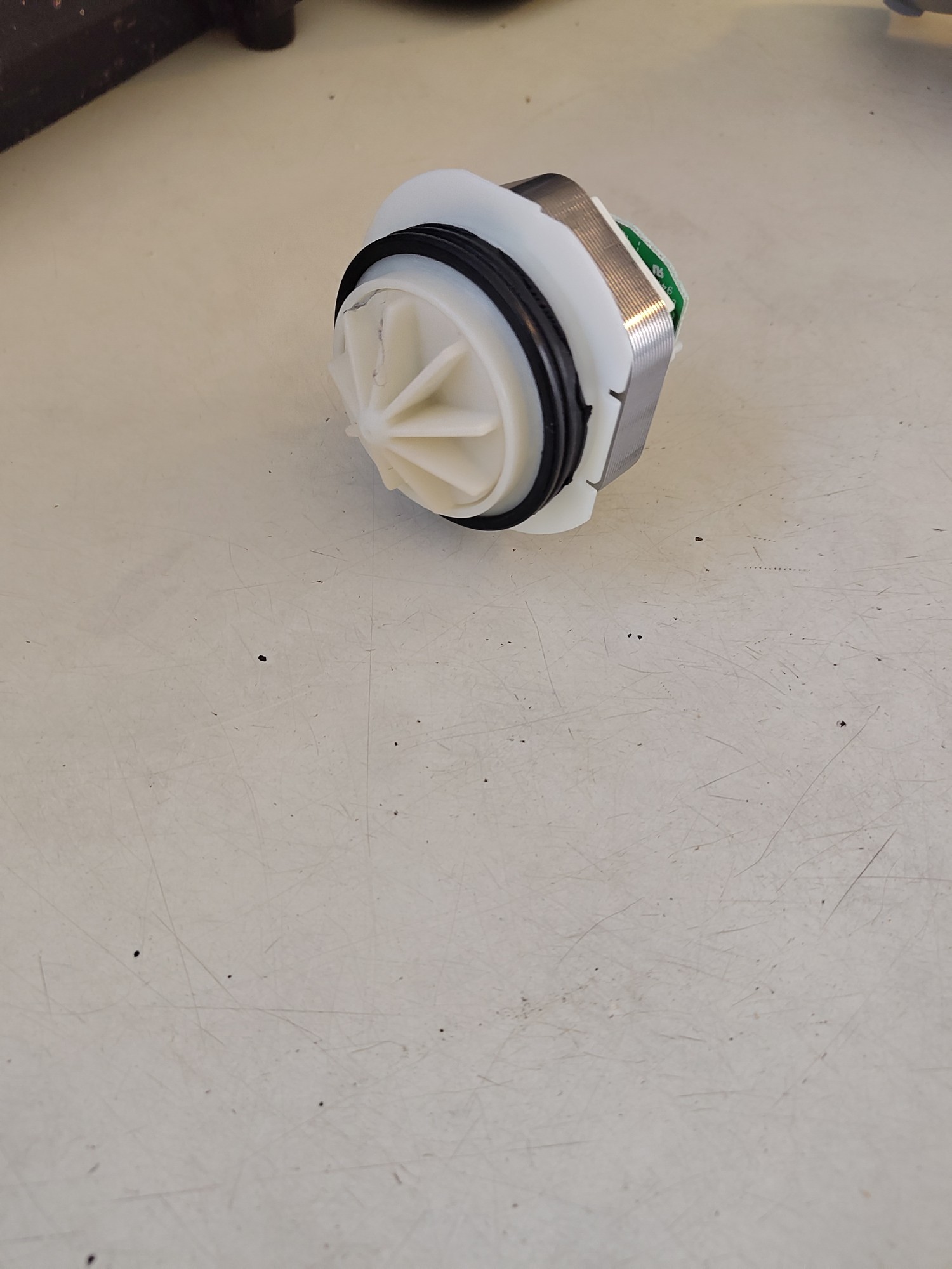
The drain pump white part spins with no obstruction at all.
With a multimeter:
My solenoid is about to get 984 OHMs resistance.
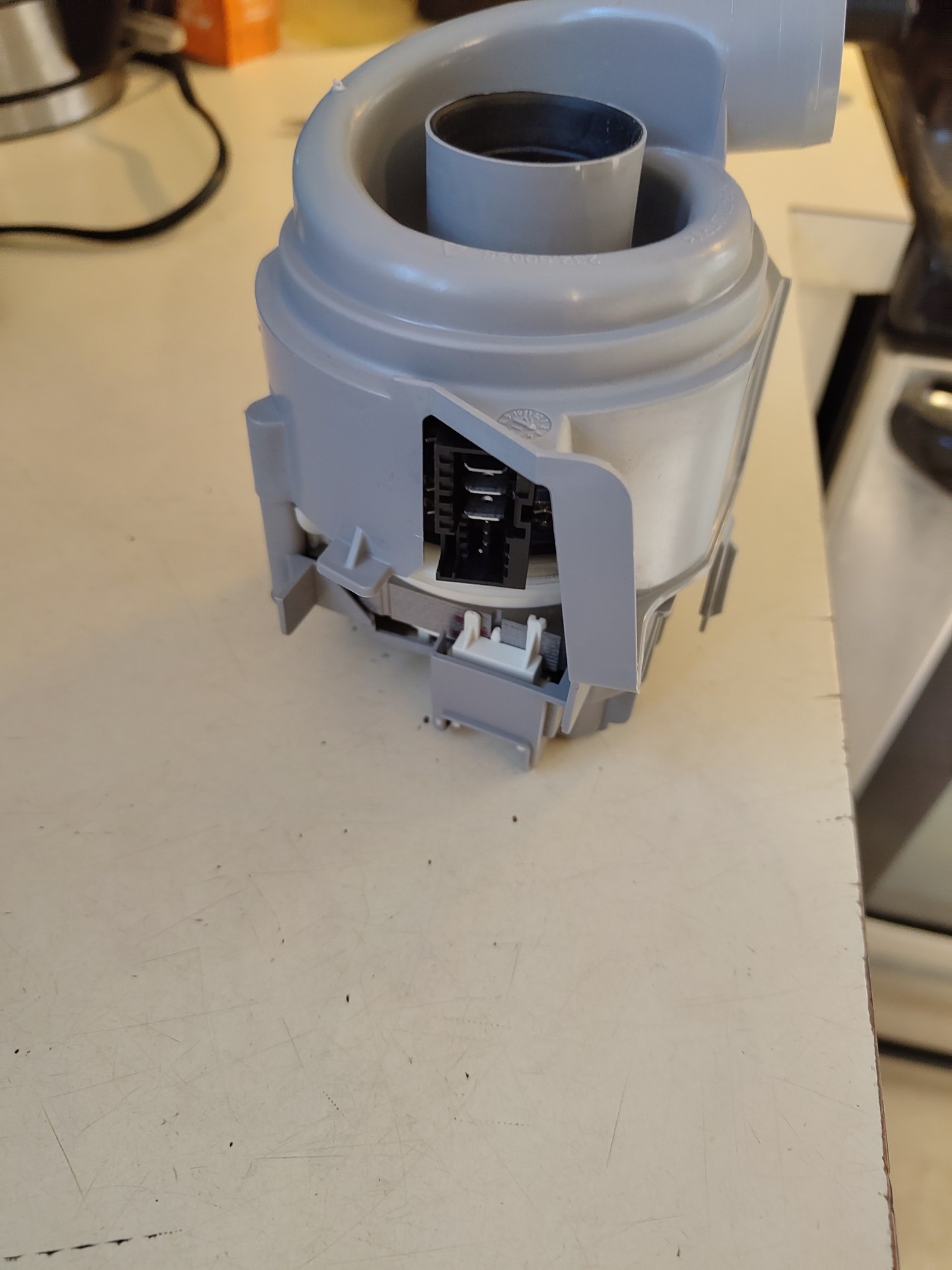
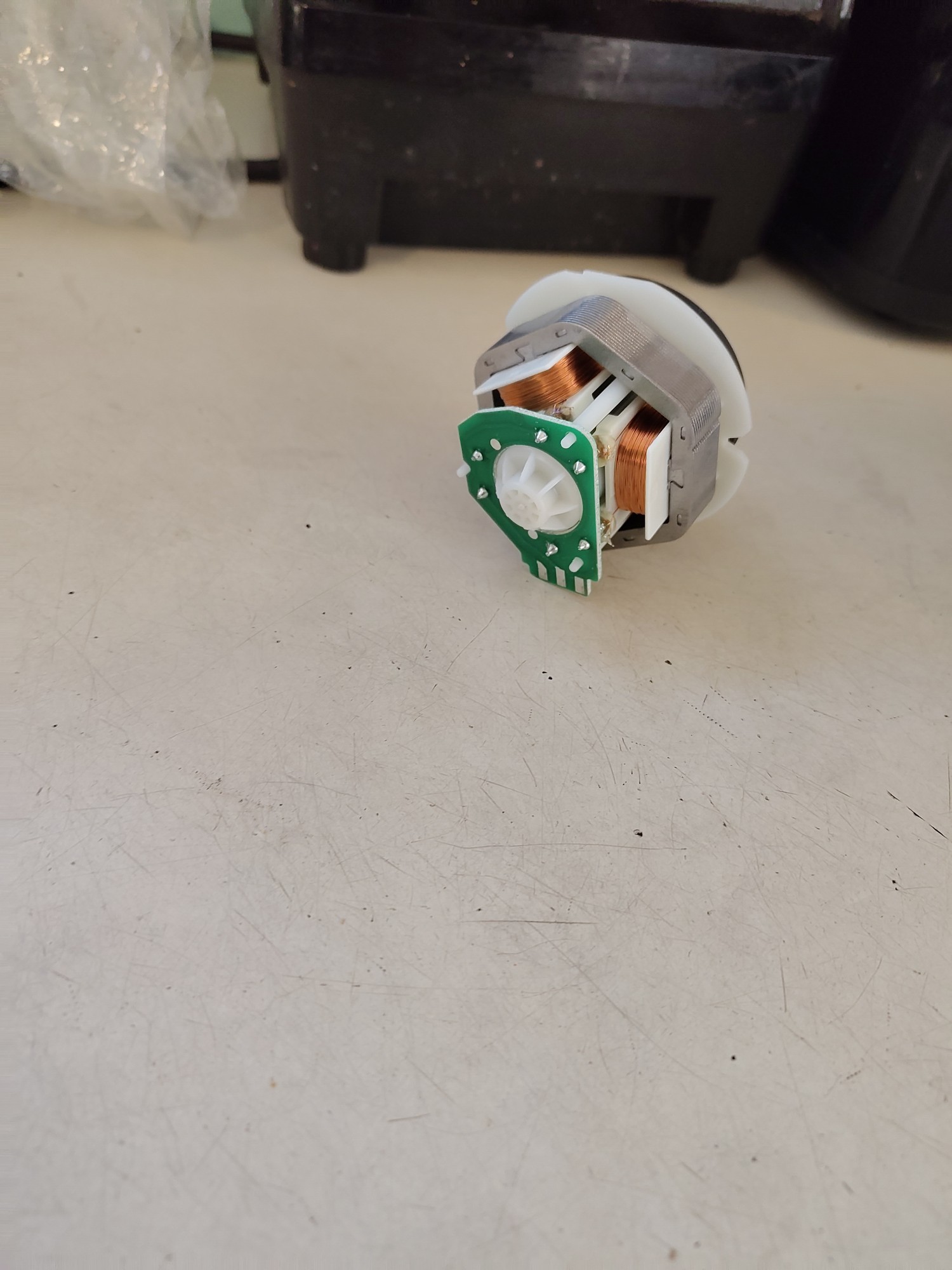
I’m not sure how to check my drain pump. I don’t see any connector end. Closest thing are these 6 metal spike thing pointed out on the motherboard.
I don’t see any visible blockage.
I’m not sure if I need to check the voltage as well. And I’m not sure if i need the dishwasher running with water to test. Problem is still stuff is located at the bottom of the dishwasher. If I wanted to check the voltage with running water.
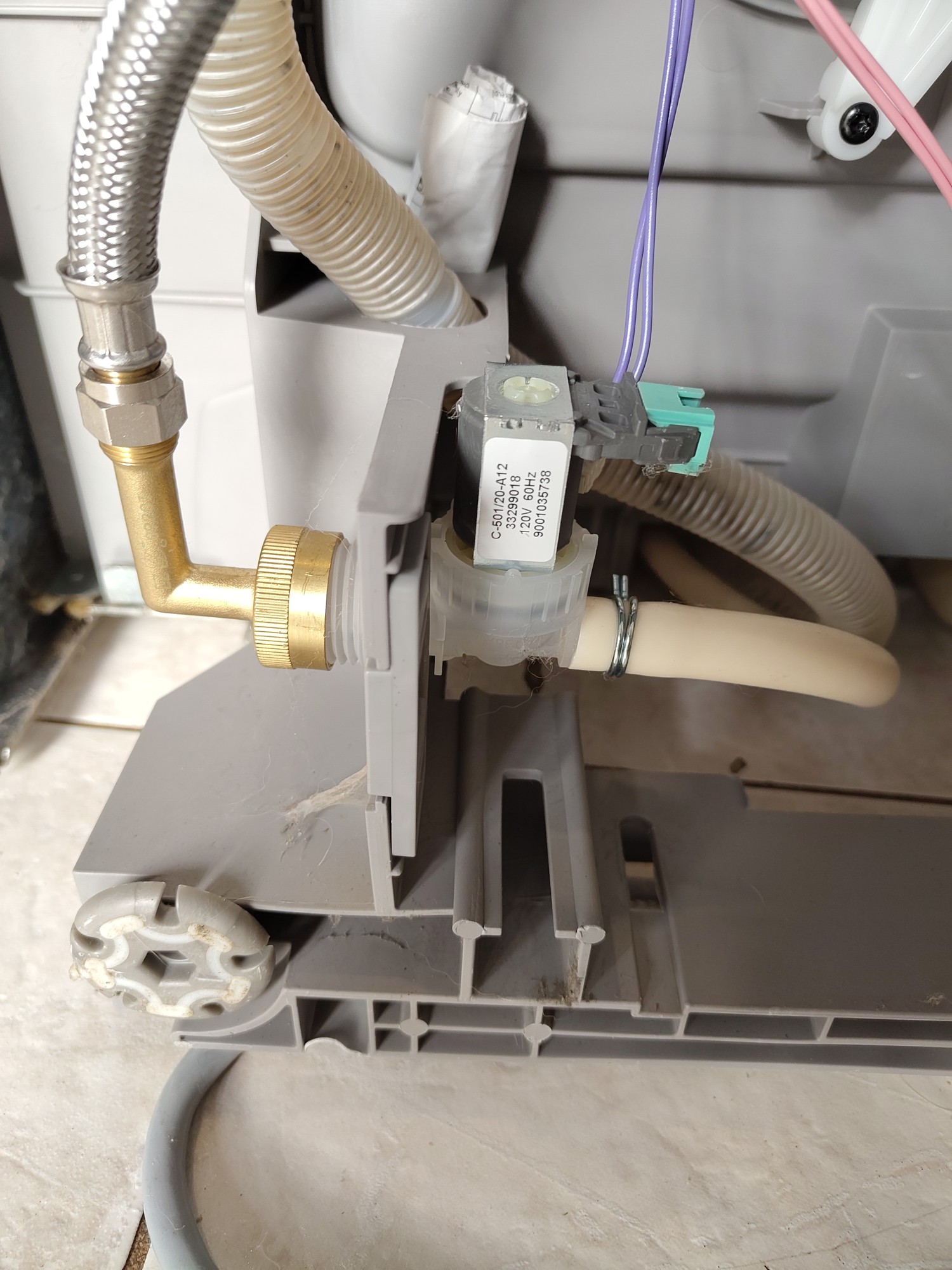
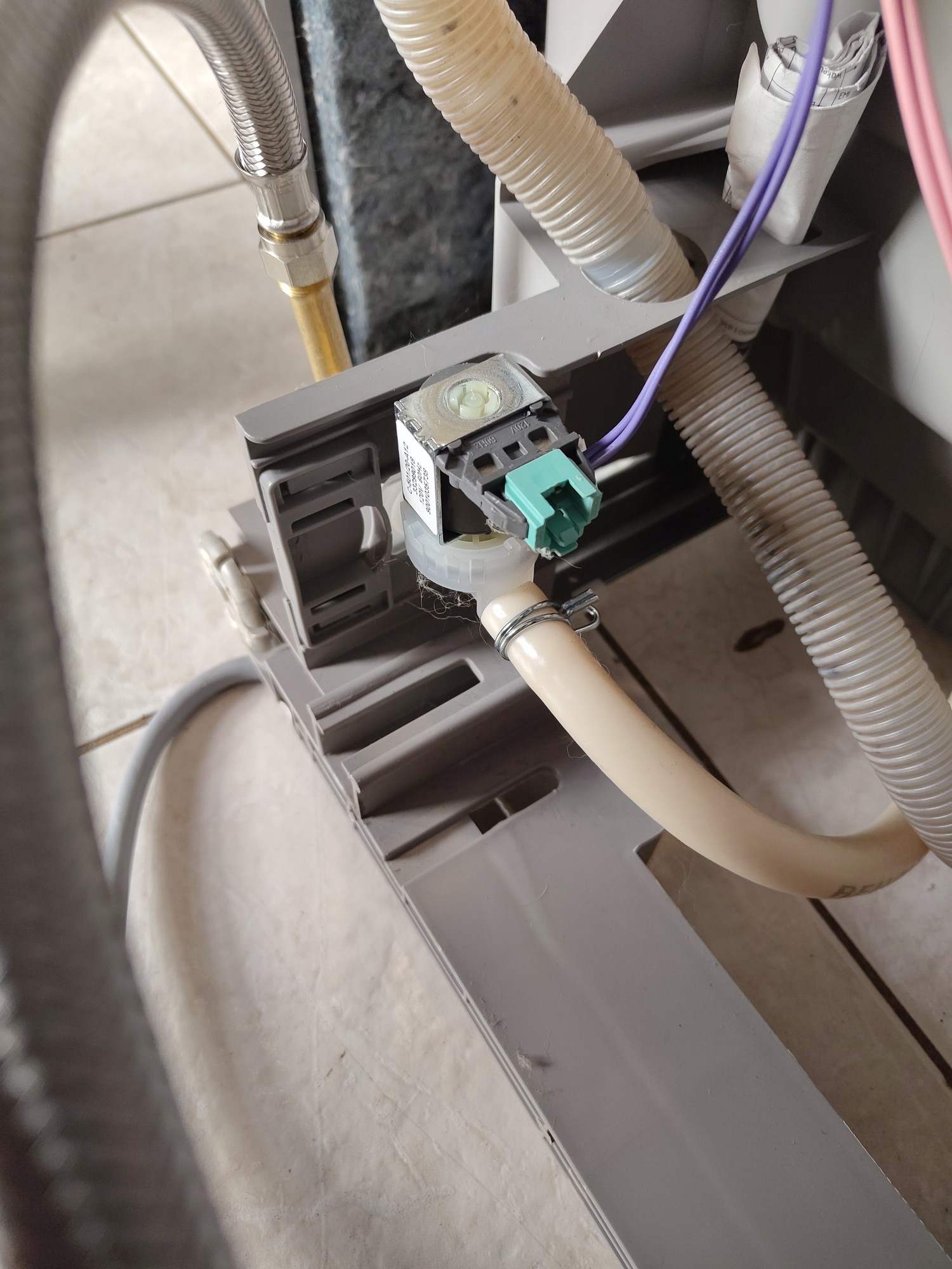
984 Ohms seem kinda high for a solenoid, might be OK though, 700 to 820 ohms would seem more resonable. In the first picture there is a rolled up paper tucked under the inlet, carefully take that out and unroll it. That will be the schematic and field tech notes, it might have the solenoid nominal resistance values and probably has a trouble shooting procedure.
Edit: fixed the solenoid value typo,
Also its not the intake solenoid if it’s filling with water.
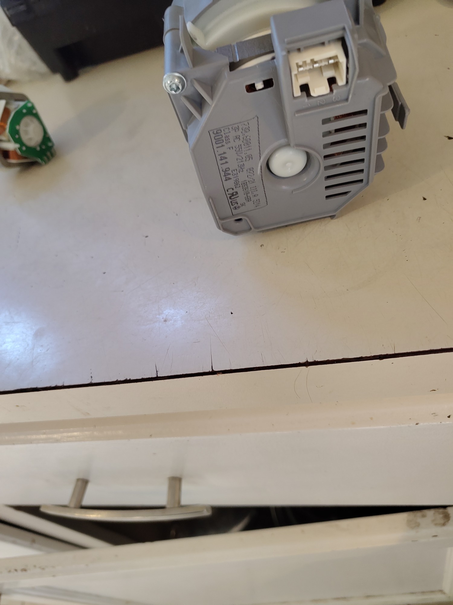
That pump motor says 3Amp 55volts AC at 215Hz that is going to be hard to bench test, and you would need the specs on the impeller to check each of the coils resistance.
Check that field tech notes and look to see if there is a diagnostic cycle that be triggered, diagnostic cycles usally allow you to step through each motor & solenoid function to see if its working. That would require putting it back together and working with it hot so don’t do it if your uncomfortable or unsure how to work on hot circuits.
I’m not quiet sure how I would go about testing like that. And I never heard of working on a hot circuit.
I understand I could time the dishwasher and use that to help find what cycle it stops at.
AFAIK you would need a VFD or a custom built driver circuit to generate the frequency you need to operate it at which is the hard part.
Honestly though if it’s an permanent magnet synchronous AC motor (highly likely) you should be able to test it provided you had a Variac to lower mains voltage (or transformer with taps works too) although you would need to bring the input voltage waaay down.
Permanent magnet synchronous motors have a ratio of V/Hz you need to maintain, in this case we have 0.256 V/Hz.
To test at 60Hz the max I would start at would be 15.34V AC at 60Hz. Otherwise you draw too much current and risk cooking it.
These are the steps. It maybe stops somewhere between step S.02 - S.09
Edit: Changed the 5s to s
So those are “S” not 5 as in step 1, step 2, step 3, etc if you hook it back up and start the “Customer Service Program” per the instructions at the top of the page the display will read out the step its on, it will do that step for the time indicated in the 3rd column and it will be doing the action indicated in the last column, then it will move on to the next step. This allowes you to watch and listen to each step to make sure its doing what it should. Find one that is not and you probably IDed the issue.
With the procedure listed you won’t have to touch the hot circuts, and you shouldnt, just listen and observe, make note of any action that is not doing what is described.
A “hot” circuit means one that has the power on.
To guide mentions buttons I do not have in order to use special function menu.
I tried asking AI, and it mentioned holding left arrow plus right arrow, then turning to changing on, and clean should flash multiple LEDs.
Delicate wash flashes and express wash stays lit when doing this. Then pressing start lights both those LEDs. Then press start again, I can hear something clicking twice, then the active and clean LEDs flash including delicate and express wash.
And if I try doing a normal wash. Some thing but the sanitise light flashes. And no water this time
The buttons aren’t labeled on the front of your machine as A B or C. But A is the button furthest to the left, B is the middle button, and C is the button on the right. Post a pic of the front of the machine with the controls or post the make and model.
Hmmm, looks like the tech sheet you have is for a dishwasher that has a 3 digit 7 segment display. Odd that it would have the wrong sheet. This looks like thee correct version for your model, follow the steps that say for shx (the first part of your model number).
Oh thank you. I understand better now.
The active and clean light are flashing which the others person shared from their diagram that it could be to drain pump.
Bosch SilencePlus 50 DBA shx3ar75uc/28
This might be the LED to service modes that can apply to yours.
https://drive.google.com/file/d/1zIHsR3agFZKQA8X5voMHcFVDxAmvW53C/view?usp=drive_link
I THINK this is for your model
The active and clean lights are flashing. So is normal washing. I’m guessing the drain pump is bad. And I don’t see anything visibly clogging it.
Those two flashing complains about the drain pump. Another comment I saw showed the drain pump cover not being pressed down all the way until it clicks in can cause it.
https://www.bosch-home.com/us/owner-support/error-codes/dishwashers#%2FTogglebox=16535672-16716986-54%2FTogglebox%3D16535672-16716986-51%2F
I can’t find the actual repair manual for that model though to decode the menu options for the service mode. Another similar display less model probably has the same meanings for the flashing LED lights. Their UI is atrocious.
Water inlet valve here shows 990-995 Ohms
As I suspected this has your resistance measurements for each of the motors, so measure where indicated (power disconected) and you can see if the windings in the motor is faulty. Your selonoid value looks good.
So you’re saying this part could be broken? Is this the drain pump?
Could it helps this part instead? What is this part called? Also a drain pump?
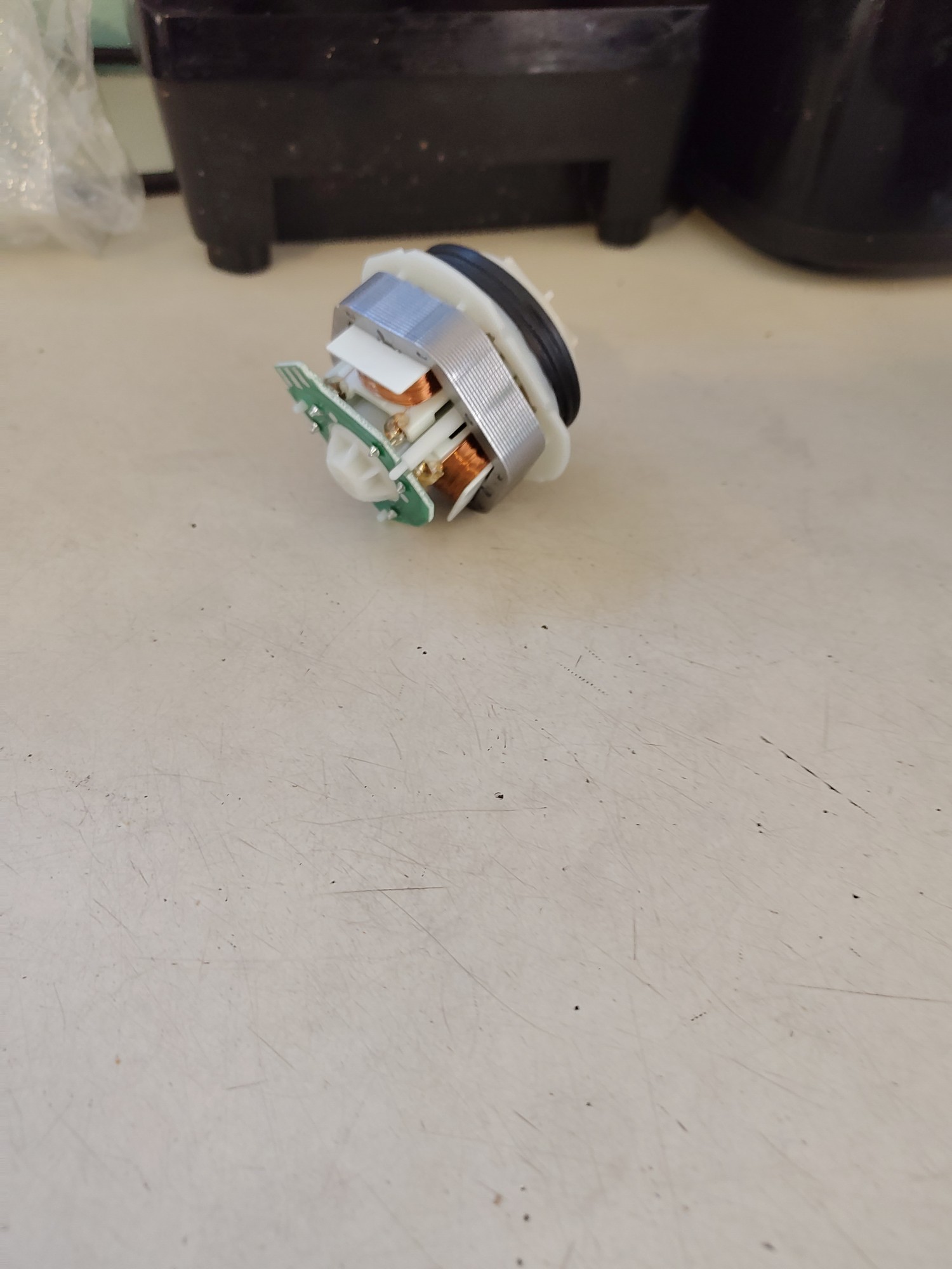
The top picture is the drain pump motor that would be the part that might need replacing if you are having a drain pump error code. Before replacing it though I would check the windings (coils) to see it they are shorted ( 0 ohms) or burned (very high or infanate ohms). If it within range it might just be that it was not seated properly in the sump housing. The sump housing I’d the gray thing in the 2nd picture.
I’m not sure where to apply my multimeter to test the coils
Closest thing I can find in this end sticking end which connects to the electronics.
Edit: Testing to the right metal parts of that connector gave me Ohms 128.8
Looks like there are 3 coils wired in a Y formation, so the silver rectangles are where the electrical contact is made, let’s call them 1,2, and 3. If you measure across any 2 points you should get the same ( or close) ohm reading. In this set up you are measuring across 2 of the coils so measuring 1 & 2 then 1 & 3 then 2 & 3 should all be simalar and should not read 0 or infinity.
1 & 2, 1 & 3 do not read
2 & 3 reads
You have a dead coil you will have to replace the motor.
Blown pump then if you can’t read anything on those pairs. They’re literally physical coils that should always pass current no matter what, and all of the smarts happens inside the control board for making the 215Hz @ 55V & 3A to feed it.